Packet Radio at 19.2kB:
Care and Feeding of the Kantronics D4-10 Radio
(Updated 28 October 1996)
by
John Ackermann N8UR
[email protected]
Copyright 1996
This document may be freely distributed in unaltered form provided credit is given to the author.
Introduction
About five years ago, Kantronics introduced the D4-10 Data Radio and brought forth the promise of plug-and-play operation at 19.2 kilobaud. Since that time, a group of hams in southwest Ohio have been using the Kantronics radios to build both an inter-city backbone, and a metropolitan area network. We now have over 20 radios in service with links covering nearly 200 miles, soon to be increased with a new 100 mile spur west to Indianapolis. The network includes both point-to-point links and full-duplex packet repeaters.
In the process, we've learned a few things. The good news is that the D4-10 does work, and you can build reasonable networks with it. The bad news is that the system isn't quite as plug-and-play as we would have liked -- it takes some effort, and often some modifications, to get a bunch of D4-10s at remote sites to reliably talk to each other.
This article outlines the tricks and tips we've accumulated during this project. We hope it will help others who want to build reliable high(er) speed packet radio networks and save them some of the learning curve we went through.
By the way, when I say "we," it's not in the editorial sense. This network is the result of significant expenditures of time and money by a number of people and groups, including the Miami Valley FM Association, the Central Ohio Packet Association, the Southwest Ohio DX Association, K1LT (who also provided most of the technical expertise), N8XX, KC8TW, K0RR, and W9ZRX.
Remi Huton, W5/F6CNB, has also kindly shared some tips that the Houston gang discovered when they implemented a network of D4-10s. His comments are interspersed throughout the text. Thanks, Remi!
The Radio
The D4-10 is a 10 watt UHF transceiver designed for data transmission. It's the same size as Kantronics TNCs -- about 5 3/4" wide by 9" deep by 1 3/4" high. It's crystal controlled with two channels. The stock tuning is for 430 MHz, although the radio will work throughout the 70cm band with only minor retuning. It's designed for digital operation, with the right bandwidth and modulation, and it has very fast transmit/receive switching -- on the bench, we have used a TXdelay as low as 6 milliseconds. The list price is $349.95.
If you have heard horror stories about Kantronics' 2M data radio, the DVR2-2, relax. The D4-10 is a complete redesign and has much better performance. In particular, the receiver front end is quite good, with four helical resonators, and does not have the DVR2-2's overload and image problems.
The D4-10 has two receiver bandwidths. The narrow setting uses a Murata CFW455B ceramic filter for a nominal 15kHz bandwidth (actually, a bit wider than normal FM voice rigs, but optimized for 9600 baud operation). The wide setting uses a discrete filter to create a 60kHz bandwidth.
The back panel of the radio has two DB9 connectors. One is an analog port that provides RXA and TXA for a 1200 through 9600 baud modem, PTT, data carrier detect (squelch derived), speaker audio, and microphone input. The other -- and four our purposes the interesting -- one is a digital port that provides TTL level RXD and TXD signals, as well as DCD and PTT.
The TXD signal drives a frequency-shift keying circuit that swings the transmit frequency 10kHz* below center for a logic 0, and 10kHz above for a logic 1. It has appropriate filtering to keep the bandwidth of the transmitted signal legal.
The RXD signal is derived from a data slicer that looks at the discriminator output. The slicer is a simple comparator that outputs a logic 0 if the received signal is below the threshold (nominally the center of the channel) and a logic 1 if the signal is above. Because the slicer uses a fixed decision point, the receiver does not tolerate frequency error as well as a system with a more complex circuit might.
The squelch circuit, which is used to generate DCD, is very fast. It opens and closes within a couple of milliseconds, and it works well with little falsing.
The radio doesn't have any metering, and the volume and squelch controls are super-sub-mini trimpots located behind small holes in the front panel. Find a good tuning tool that fits the trimpots, and don't lose it! Also, if you're a chronic twiddler, you might want to find some replacement pots and keep them on hand -- it's easy to break the trimpots if you treat them roughly.
Unless ordered otherwise, Kantronics ships the D4-10 with crystals for 430.55 MHz. Although we are using a number of different frequencies in our network, we made the decision to leave 430.55 as channel 1 in each radio, and put our working frequency in channel 2. That way, any two radios can communicate with each other if necessary. We've also left 430.55 as a testing and experimental frequency without any full-time activity.
Modulation Methods
You can plug any 1200 through 9600 baud modem into the analog port, but if you use a D4-10 for that you're spending money for radio features you don't need. The D4-10 is really designed for 19.2kB operation, and the rest of this article focuses on use at that speed..
Kantronics offers a 19.2kB modem based on the G3RUH design, called the DE19k2. It plugs into the DataEngine TNC, and can be hardwired to other TNCs. But I recommend that you don't use any separate modem at all.
Hang on, hear me out. The D4-10 is really an RF modem -- one end of it (the antenna connector) deals with analog RF energy, while the other end (the TTL level I/O port) handles digital signals. Adding a Kantronics 19k2 modem doesn't add any functionality that isn't already present in the radio. You can simply hook the RXD, TXD, PTT, and DCD outputs of a TNC2 modem disconnect header (or equivalent) to the TTL port on the back of the D4-10 with no other interface circuitry, and it will work just fine.*
We've interfaced the D4-10 as an RF modem to the:
* PacComm Tiny-2 TNC (speeded up with 10MHz crystal);
* Kantronics DataEngine (using a simple jumper board inside the TNC in place of a modem card -- details below); and
* Ottawa PI card (a PC plug-in card designed for use with KA9Q NOS and the GRAPES 56kB modem -- it's the best performance for the buck packet generator you can get, if you're willing to run only NOS as your packet software).
All interoperate just fine. Note, though, that this scheme won't interoperate with radios using the Kantronics 19k2 modem because the Kantronics modem does data scrambling and the RF modem configuration doesn't. You'll need to take one road or the other in your network.
Doing it on the Right Frequency
Without a doubt, keeping the D4-10 on frequency is the biggest challenge in using these radios. The radio apparently wasn't designed with remote link use in mind, and consequently in the real world of transmitter buildings that aren't climate-controlled, frequency drift is a real problem.
The baseline to remember is that the frequency difference between a D4-10 transmitter and the receiver it is talking to can theoretically be up to about 4.3 kHz (half the nominal FSK of 9.6kHz) before the system stops working. Practice bears this out -- systems will talk to each other pretty reliably within 4kHz or so (which just happens to be 10 parts per million at UHF). Unfortunately, it's easy for a pair of D4-10s operating in different environments to move that far apart.
Starting at the beginning, the D4's oscillator is a simple inductance-tuned design that doesn't use much in the way of temperature compensation. The crystal specification isn't too strict -- according to Savoy Electronics (now defunct), Kantronics' original crystal supplier, the original spec called for 30ppm stability over -10 to +60 degrees C (though the crystals Savoy shipped were actually designed for +/-8ppm over that range).
In September, 1992, the spec was tightened (at an increased cost of a buck or two per crystal) to +/- 5ppm over -10 to +60 degrees. In early 1993, Savoy went out of business and Kantronics now gets crystals from Frequency Management in California. We don't have a full crystal spec sheet from them, but they say their crystals are spec'd to 5ppm. Our subjective experience, by the way, is that the FM crystals are significantly better quality than the Savoy rocks were.
However, even with the new crystals we see frequency drift much greater than the crystal spec would account for. My (unscientific) guess is that the inductor in the oscillator is contributing much of the thermal instability. We've also seen a few cases where the MC3362 IC seems to be the source of significant receiver drift.
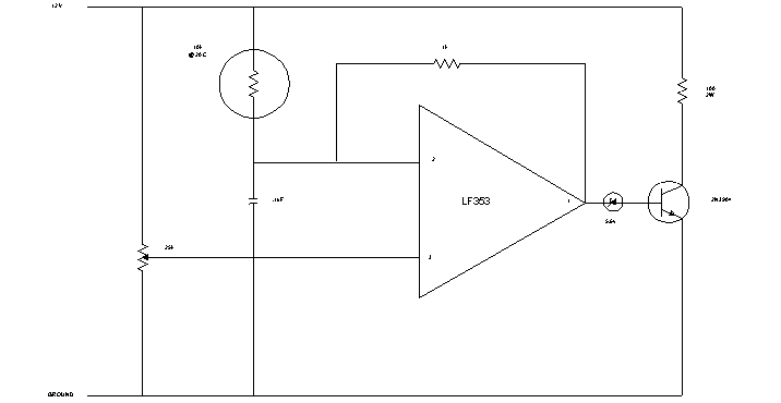
Regardless of the cause, we've found it a major struggle to keep a pair of radios located at non-temperature controlled sites within tolerance. In the past, we've built a simple proportionally controlled heater to maintain the interior of the radios at a constant temperature of 40 or so degrees C. A schematic of the heater circuit (designed by K1LT) is shown in Appendix A.
We build these heaters on a small piece of perfboard about 3/4 inch by 1 inch, and put one mounted over the crystals in each radio. In some of the radios that seem to have drift in the '3362 IC, we put a second heater over that chip as well. The warmth doesn't seem to do the other components in the radio any harm. We've used various methods to help improve the temperature stability in the area of the crystals; a piece of a Styrofoam egg carton can make a nice enclosure with a bit of whittling (thanks to W9ZRX for that idea).
There's now another alternative: Dave,
W9ZRX, has found that Murata makes a clip-on crystal heater that
works very well. You'll need one heater for each crystal you
want to stabilize. At present, the only known source for small
quantities is the Yaesu service department - they use these heaters
in their repeaters. Here's the pertinent information:
Yaesu's phone number is (800) 255-9237, and shipping/handling has run $4.00 per order.
With either heater installed, one problem arises: how do you trim the oscillators without losing temperature stability (though this is less of a problem with the clip-on Murata heater)? The simplest answer is to drill 4 small holes in the top of the case, to provide access to the four trimmer coils. After tuning, cover the holes with a piece of tape to prevent destabilizing air currents. (Tuning this way has another advantage: some radios will shift frequency by a few hundred cycles when the cover is put back on and the screws tightened down. Tuning with the cover on avoids this annoyance.)
We've found with heaters installed, the frequency drift problems have pretty much gone away at our remote sites. The biggest remaining problem has been in the summertime, when at one or two locations the ambient temperature has been high enough that the radio temperature goes above the setpoint of the heaters.
Setting the heater to a higher temperature could minimize this problem, but we've discovered that crystals at 50 degrees may not trim properly, and it may be necessary to increase the value of the fixed inductor in series with the trimmer inductor to be able to trim the crystal at this higher frequency. So far, we've left the heaters at 40 degrees and avoided this problem.
Dave, W9ZRX, did some more good work
here. He has had International Crystal develop a specification
for D4 crystals rated at 50 degrees C. Here's the information:
| Receive (old formula): | |
| Receive (new formula): | |
| Transmit: |
With standard delivery times, the crystals are $13.45 each, plus $5.00 shipping/handling per order. International's number is (800) 725-1426. The International engineer that Dave worked with is named Mark Handley; he's a good contact for crystals and specs not in the International catalog.
I suggest using these crystals in radios with heaters, as we've seen some of the older crystals cut for room temperature drift beyond the adjustment range after a couple of years with the heat on.
Remi Huton reports success dealing with frequency drift by using a demodulation method that tolerates a bit more drift. Here are his comments (note that this will only work if you are using a G3RUH-style modem -- it's not applicable to the direct FSK scheme we recommend above):
"The first consideration is that a real G3RUH 9600 modem is more tolerant of frequency drift than the 19.2K Kantronics one.
"Instead of using the D4-10 internal data slicer, we are now using the analog output of the radio for receiving the data. The input filter [ of the modem ] has been modified by dividing by two the values of C16, C17, and C21, and JP12 has been moved to "A". These modifications are similar to the ones recommended by G3RUH to operate his modem at 19.2K.
"You also need to wire a Y connection between the D4-10 and the Data Engine, with PTT and TXD going to the TTL port and RXD coming from the analog one.
"This modification was applied to all our systems about 9 months ago and has eliminated the need to drive to the nodes to readjust their frequencies."
Tuneup
In the process of learning thermal engineering, we did a lot of radio tuning and tweaking. We've developed a tuneup process that's a bit different than the one Kantronics describes, but works well.
First, the RF stages of the radio don't need much tweaking at all. The radios come from the factory tuned for the 430 MHz range, and though we've moved some of them down to 420 MHz, that 10 MHz shift required only a minor touchup of the four receiver helical resonators; the transmitter didn't require any adjustment at all. On the other hand, if you have a SINAD meter handy, you can often pick up a dB or two of receiver sensitivity by retuning the helicals, even if you're not moving the frequency much.
To put a D4-10 on frequency, first follow the manual's instructions to adjust the PLL center frequency for each crystal. This is a simple -- but touchy -- process of adjusting a small potentiometer for a 2.50 volt reading at a test point.
A. Transmitter
To net the transmitter, simply look at the transmit frequency and adjust the appropriate trimmer coil while keying the PTT line on the analog I/O port. Then key the radio using the PTT line on the TTL port. The frequency should be 10kHz lower than you saw before. If the shift is off, adjust R11 to correct it. To check the linearity of the modulator, tie the TTL TXData line high and key again; you should now see a frequency 10kHz above center.
Note that some crystals may swing further than others for a given setting of R11; we recently encountered some rocks from Kantronics' new supplier, Frequency Management, that wouldn't pull 10kHz even at R11's maximum setting. FM has modified their spec to deal with this problem, and it hasn't recurred.
It's important to make sure that you're getting at least 10kHz shift from the transmitter; if the shift is too narrow, performance falls off drastically.
B. Receiver
Putting the receiver on frequency is a bit more complicated. You could just look at the local oscillator output with a counter, but doing so wouldn't take into account any error in the receiver's other oscillators. By far the most reliable -- and the fastest -- way to net the receiver is to use an on-frequency signal source and an oscilloscope. The signal source could be an FM transmitter modulated with an audio oscillator, though a real FM signal generator will make the tuneup easier. The scope only needs to handle audio frequencies.
Here's the process:
1. Make sure you've adjusted the appropriate VCO steering pot as described in the Kantronics manual.
2. Set the signal generator to the receive frequency, and apply FM at around 5kHz deviation. Set the generator output to 2 or 3 microvolts. Connect the signal generator to the D4-10's antenna connector.
3. Connect the oscilloscope to the RXData line (pin 5) of the TTL I/O port. Set the scope up to handle a 1000 Hz waveform, DC coupled at 5 volts peak to peak. Connect a speaker to the radio, open the squelch, and adjust the volume for a comfortable level.
4. Set the radio's receive bandwidth selector to the narrow position.
5. Listen to the audio output and adjust the receive trimmer coil until you hear the signal with minimum distortion. The goal is to get the receiver into the ballpark during this step -- don't worry about high accuracy.
6. Remove the signal from the D4-10's input and look at the RXData line on the scope. You should see two horizontal lines, representing logic zero and one, with noise in between them. There may be an imbalance -- more intensity on one of the rails than the other (in fact, there may be only one rail visible). Your goal is to adjust R17 -- the data slicer threshold control at the rear center of the radio's PC board -- to produce equal intensity at both rails. This will put the slicer switching point at the center of the noise passband. An error in this setting means that the transmitter at the other end won't have the best chance of getting its data decoded. After adjusting the data slicer, don't touch it again -- the later tuning counts on it staying put..
7. Reapply the signal generator to the radio, and reduce the deviation to about 3kHz. Make sure the signal is fairly strong (100 or more microvolts). Set the D4-10 bandwidth to the wide position. You should see a square wave on the oscilloscope. Now, adjust the receiver trimmer coil for an equal duty cycle -- the upper and lower halves of the square wave should be the same width. When you've accomplished that, the tuneup is finished.
Note: Remi Huton suggests peaking up the discriminator coil, L19, for maximum audio output prior to adjusting the frequency.
By tuning this way, we ensure that the whole receiver is aligned to the nominal frequency; the data slicer will be aligned to the middle of the passband, and the local oscillator setting will take into account any error in the preceding oscillators.
Using a sine wave of fairly narrow deviation allows more accurate frequency setting than a square wave at full deviation, which will provide little resolution within the tolerance range.
It's also instructive to look at the output on the TTL RXData line while varying the signal generator output; you can get a good feel for how much signal is necessary to generate a solid output waveform, and what happens when the signal is off frequency. Hooking the scope to pin 5 of the analog output port (the "RXA" output) will show you what the signal looks like before the slicer gets it.
I've built a scope cable for this tuneup process that is terminated with a DB9 connector (the center of the coax goes to pin 5). I can plug this cable into the analog port to look at the quality of the received signal, or into the digital TTL port for alignment. That, and another cable with a simple switch wired to pin 3 (the push to talk line) of a DB9 greatly speed up the alignment process.
As a final tuneup note, when I'm aligning a radio outside the case, I usually tune about 500 Hz high; putting the radio back in the box and tightening things down, together with the warmer temperature inside the enclosure, tends to move the frequency down a bit and starting out a bit high compensates for this.
Miscellaneous Modifications and Tips
A. Cable Pinouts
Here's a table that shows the connecting
cable pinouts from the D4-10's TTL port to various TNCs:
| Description | |||||
| TX Data | |||||
| DCD (Squelch) | |||||
| PTT | |||||
| RX Data | |||||
| Ground |
* Except for PTT, all signals from the TNC-2 come from the modem disconnect header inside the unit. You'll need to ensure that header pin pairs 1-2, 17-18, and 19-20 are not strapped together.
B. Gating the RXD line.
Some TNCs have trouble dealing with the random transitions that are present on the TTL RXData line when there's no signal present. In the Kantronics DataEngine, this shows up as lost packets in KISS mode, and the serial port's inability to run well at high speeds. When using the Ottawa PI card,* the whole computer in which the card is installed may slow to a crawl if the data slicer threshold isn't set properly -- we've seen cases where characters typed at the keyboard don't echo to the screen for up to a half second because of this problem.
The difficulty is that the HDLC chip (the 8530 SCC in both the DataEngine and the PI card) should generate interrupts to the CPU only when there's a real signal present, but noise on the RXD line can fool the chip into generating tons of spurious interrupts that can bring the CPU to its knees.
A simple fix: install a small-signal diode (1N914 or similar) between pin 2 of the TTL DCD connector, and pin 2 of U1. The cathode of the diode should be at U1. The diode can be installed on the bottom of the radio's PC board; the two tie points are close together.
This will cause the DCD signal to clamp off the data slicer when the squelch is closed; when the squelch opens, the slicer works normally. Note that if you do this, you'll need to open the squelch to go through the tuneup procedure described above.
C. Transmit frequency shift modification.
Some D4-10s exhibit an unwanted frequency shift during transmit. This is due to RF getting into the analog modulator circuit used for 9600 baud and slower packet; the RF is rectified in U5 and causes a DC bias shift at the modulator. Kantronics recommends installing a 470pf capacitor between U5 pin 11 and U5 pin 12. Recent production radios have this mod included.
An alternative approach is to yank out C59, a 220 uF electrolytic that's the coupling capacitor for the analog TX data signal. Pulling this cap kills the analog TXA input (so the radio won't work with a 1200 or 9600 baud modem) but it isolates the FSK circuit and reduces the likelihood of incidental modulation or frequency drift.
D. Unwanted interaction between R17 and Receive Frequency.
Due to a PCB error, changing the setting of the data slicer threshold control, R17, causes a shift in the receiver local oscillator frequency. The problem is that the D4-10 has the capability of using a DC voltage to correct the receiver frequency for satellite Doppler shift; there's a varactor diode on the receive oscillator for this purpose. Unfortunately, the voltage driving that varactor is derived from the wiper of R17, rather than the top end as intended. So, when you adjust the data slicer threshold, you also shift the receive frequency a little bit.
This problem was fixed by a trace cut and jumper wire moving the connection point for the varactor off the wiper of R17. If your radio has a jumper wire on the bottom of the PCB, it has the fix installed.
However, the good news is that if you tune the receiver as described above, you don't need to worry about a hardware fix. Our tuneup method leaves R17 alone after the initial setting against passband noise; since we only adjust this control before setting the local oscillator, there's no danger of walking the frequency away from where it should be.
E. Crystal Changes
In December, 1993, Kantronics modified the D4-10 IF frequency slightly to deal with a receive spur. The high IF was changed by 15kHz, and this resulted in a slightly changed receive crystal formula. The old formula was (Fo-45.000)/64; the new one is (Fo-44.985)/64.
We plugged an old crystal in a new radio and found that it would just barely net to frequency (at room temperature) with the trimmer slug bottomed out. We haven't been able to try a new crystal in an old radio yet. The moral is to make sure you specify the proper crystal to go with your radio.
Kantronics' current crystal supplier is:
Frequency Management
15302 Bolsa Chica St.
Huntington Beach, CA 92649
(714) 892-3234
(800) 800-9825
The order numbers are:
| Receive (old formula) | 453-600-2 |
| Receive (new formula) | 453-601-2 |
| Transmit 453 | 453-600-1 or 453-601-1 |
(I have TX crystals that were tagged with both numbers; the TX number apparently tracks the RX with the "-1" suffix instead of "-2".)
At the risk of repetition, here's the
order information for the 50 degree ICM crystals for use with
a heater:
| Receive (old formula): | ICM 685250 |
| Receive (new formula): | ICM 685252 |
| Transmit: | ICM 685249 |
With standard delivery times, the crystals are $13.45 each, plus $5.00 shipping/handling per order. International's number is (800) 725-1426. The International engineer that Dave worked with is named Mark Handley; he's a good contact for crystals and specs not in the International catalog.
F. Discriminator Distortion
Remi Huton reports that R8 and C23 in the discriminator output circuit affect the frequency and phase response of both the TTL and analog outputs of the D4-10. He recommends removing R8 to solve this problem, but notes that he hasn't quantified what difference in BER the change makes.
G. Missing R72
Remi also reports that R72 (43k) was missing on several of the radios he looked at. Without this resistor, the discriminator response is a bit too narrow. He advises checking your radios to make sure that R72 is in place. Using a lower value for this resistor will improve the frequency tolerance, but reduce sensitivity.
H. Cruddy VCO Potentiometers
Both Remi and we have noticed that on some radios the four pots that are used to "steer" the PLL to the right starting frequency get sticky, noisy, or otherwise troublesome. He's replaced these pots with multi-turn ones; we've just put up with it.
RF Paths
Just a quick comment on using UHF for data links: make sure you have a line of sight path! From actual experience: a 45 mile truly LOS path works well; a 15 mile path with foliage and hills in the way didn't work (actually, it worked marginally before the leaves came out; when the trees were full, the path stopped entirely).
The 10 to 12 watts coming out of the D4-10 is in a 60kHz bandwidth instead of the 15kHz we're accustomed to with voice FM paths. The D4-10 acts pretty much like a 3 watt transmitter running voice. The receiver is typically from .5uV to .8uV for 12dB SINAD in 60kHz bandwidth (about .3 to .4 uV in the narrower bandwidth).
Although we can span reasonable distances
with barefoot D4-10s, my Christmas wish is for a 40 watt power
amp with fast enough turnaround time to work with the Kantronics
radios. The 6dB boost would improve the margin on a lot of our
paths. Unfortunately, no one makes a PIN-diode switched UHF amp,
so that's probably Yet Another Construction Project to work on.
Conclusion
I'll reiterate what I said at the beginning: the D4-10 can be used to build a reliable packet network that will move data pretty quickly. This may seem like a long article devoted to the shortcomings of the radio, but now that we've learned all this stuff, keeping the network working, and adding to it, isn't much of a chore. Over the last year -- since we got the heaters installed -- almost all of the (relatively few) problems we've had have been the same ones that plague any RF system: antenna problems, power supply failures, and the like.
Appendix A
Heater Schematic
Appendix B
Using the DataEngine and D4-10
Without a Modem
The Kantronics DataEngine requires internal jumpering to connect its circuitry to the DB-15 connector on the rear panel. Normally, a Kantronics modem provides this function, but when operating the D4-10 as an RF modem, you need to find an alternative way of routing the signals.
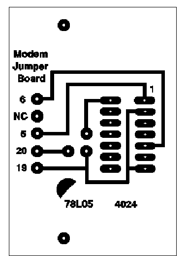
The easiest way to do this is to use a small jumper board that's available from Kantronics for about $20 (it's called, cleverly enough, the "DataEngine Jumper Board"). The board provides a watchdog timer and PTT circuitry, as well as signal routing.
There's one modification that you need to make before using the jumper board with a D4-10. For RF modem use, we tell the DataEngine to treat the D4-10/jumper board combo as a "Type A" modem -- like the 1200 baud modem. In this configuration, the DataEngine provides a transmit clock frequency of 32 times the baud rate, and expects the modem to provide a receive clock at the baud rate. We need to add an IC to the jumper board to divide the TRxC signal by 32 and route it back to the RTxC signal.
A CD4024 CMOS IC can do this nicely. There's room on the jumper board to mount the chip upside down, and you can use "dead bug" wiring to hook things up. If you're using a CD4024, pin 1 goes to pin 5 of the "A_INT1" header on the board (an easy connection point is the INT side of JP3), and pin 5 goes to pin 6 of either the A_INT1 or A_EXT1 headers, with a 100k pulldown resistor to ground (the pulldown doesn't appear to be necessary, but Kantronics uses one in their DE1200 modem). Make sure the reset line (pin 2 on the CD4024) is tied to ground. You can pick up 5 volts Vcc for pin 14 of the chip from the LM78L05 regulator on the board -- the top of R2, or the junction of R5 and R6, will do.
A CD4020 chip will work instead of a CD4024, if that's what you have handy. Use pin 10 as the clock input, pin 5 as the output, pin 8 as ground, and pin 16 as Vcc. The 4024 doesn't have a reset pin to worry about.
If you want to do a prettier job, on the next page is artwork supplied by Dave Zeph, W9ZRX, for a small PCB that can mount on the modem tie-down pillars in the DataEngine.
The jumper board needs to have JP6 on and JP7 off to make the DataEngine think it's a "Type A" modem. On the software side, you need to provide the DataEngine with the clock speed and tell it to use external DCD. With the standard DataEngine firmware, the command:
MODEM 2,HALF,19200
will set things up correctly. The DataEngine is affected in an unhappy way by random noise on the RXD line, so you'll want to be sure you've installed the RXD clamping modification described earlier.
The jumper board uses different pinouts on the DataEngine's DB15 connector than the Kantronics RUH modem. Make sure you have the correct cable connections (see the section on cable wiring, above).