The TASS Coaxial Relay System
The TASS (Totally Awesome Switch System) is a general purpose RF switch for use from DC to 150 MHz. It is designed to more-or-less replace the HP 59307A coaxial switch for computer-controlled signal routing. It also has a number of uses in ham and SWL radio operation, such as switching receive antennas, filters, and transverters.There are two boards in the system: the TASS-R relay board, which is by far the most interesting, and the TASS-SHIELD board for use with an Arduino Mega 2560 microcontroller. The TASS-SHIELD and open source software from TAPR allow up to 4 relay boards to be connected in a system.
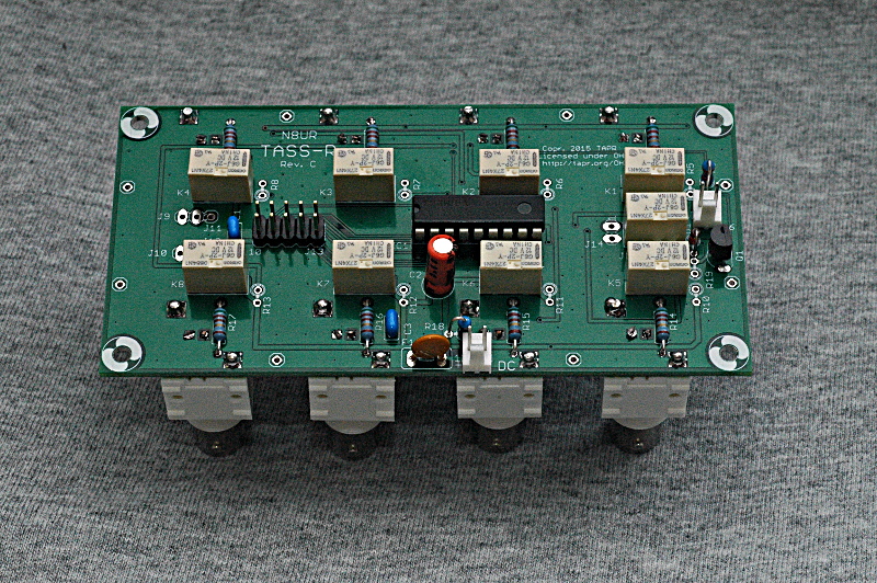
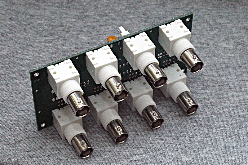
The TASS-R board has 8 connection ports grouped into two busses. Each port connects to its bus via an individually-controlled relay. External connectors may be added for increased flexibility as shown in the "Use Cases" section below. The TASS-R is designed to be used with the TASS-SHIELD though it can be used with any controller that provides 9 digital outputs. Mechanical switches can also be used.

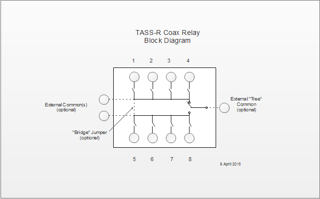
Block Diagram
Use Cases
Since each relay on the TASS-R is independently controlled and more than one relay may be selected at the same time, the board can be used in many different configurations:
- Two 3-way switches using e.g. ports 1 and 5 as commons.
- Two 4-way switches using external connectors as commons.
- One 7-way switch using jumper and e.g. port 1 as common.
- One 8-way switch using jumper and external connector as common.
- One 8-way switch using K9 and external connector as common.
- Variants 1 or 3, but configured for any-to-any use (e.g. first connect port 3 to port 7, then connect port 6 to port 8).
Software
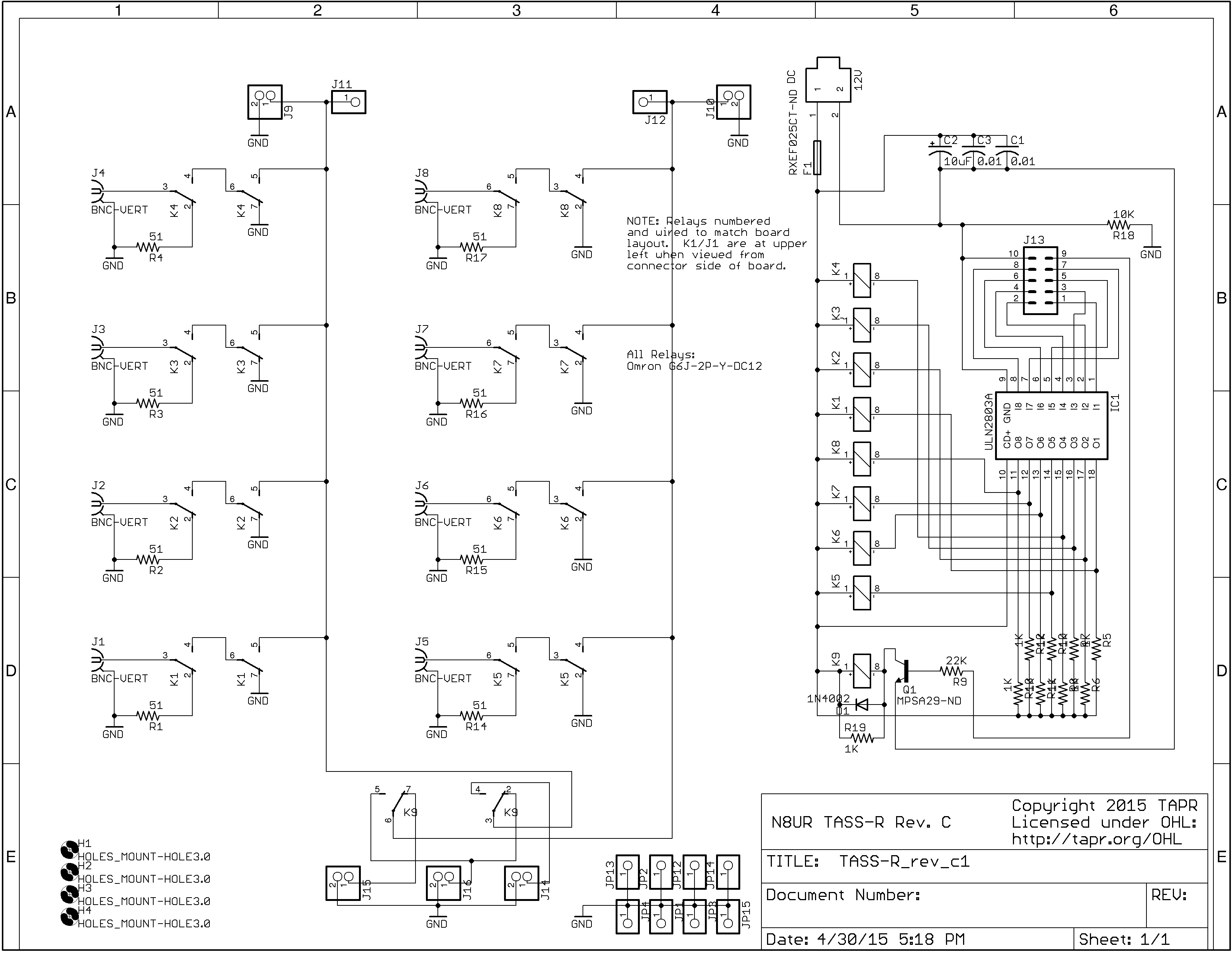
The TASS-R is designed to be controlled by a microcontroller such as an Arduino or PIC. The test software is written for the Arduino. I'll provide more detail elsewhere, but the idea is that the relay board has an independent control line for each relay. The Arduino mates with the TASS-C shield, which connects to the TASS-R via a 10 pin ribbon cable. The user issues commands to the Arduino via USB or network connection; the shield sets the appropriate relays.
Here is the current command syntax:
- All commands are delimited by angle brackets ("<" and ">")
- The first character selects the board, A - D
- The second character selects the relay, 0 - 8 ("0" clears all relays)
- The third character selects the operation:
- "H" -- set this relay and Hold it until explicitly cleared
- "S" -- Set this relay and clear other un-Held relays
- "U" -- Unhold this relay (clear it and return to normal use)
- "H" -- set this relay and Hold it until explicitly cleared
- Total command length is therefore five characters
For example:
- <A0U> # Clear all relays on board A
- <A1H> # Set board A, relay 1 and hold (use as common)
- <A2S> # Set board A, relay 2
- <A3S> # Set board A, relay 3, and clear relay 2
- <A4S> # Set board A, relay 4, and clear relay 3
- <A1U> # Clear and unhold relay 1 on board A
- <A4H> # Set board A, relay 4, and hold (use as common)
- <A1S> # Set board A, relay 1
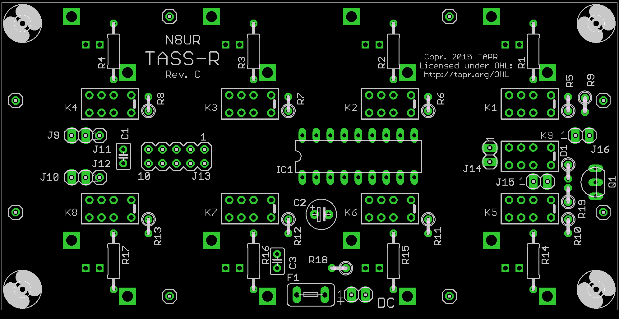
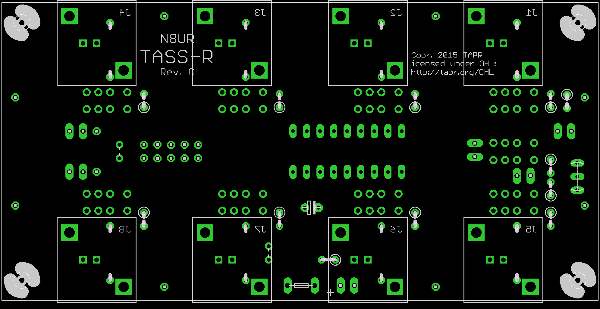
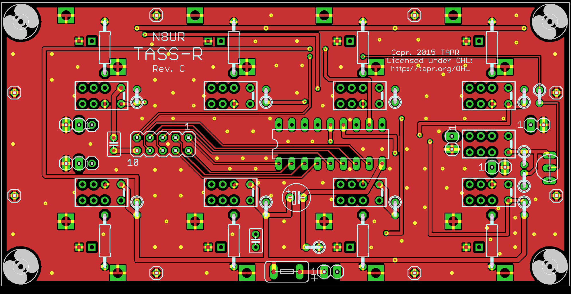
Schematic and Layout
Top Placement
Bottom Placement
Layer 1
Layer 2

Layer 3

Layer 4
