The MVUS FMT:
October 2007 W8KSE Station Description
W8KSE Transmitter Site
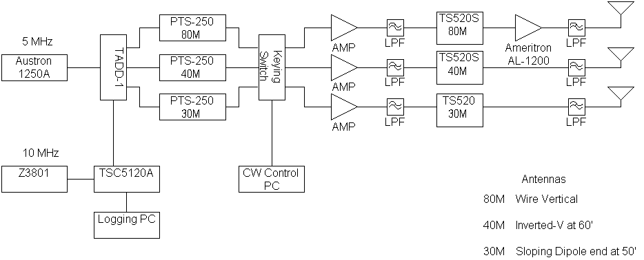
The FMT was hosted at Mike (W8RKO) Suhar's station, located south of Dayton, Ohio at 84 08' 12" W, 39 40' 02" N. Equipment was provided by Mike, John Ackermann, N8UR, and an anonymous contributor. Bruce Raymond, ND8I, did a lot of work on the RF gear.Here is a block diagram of the setup described below.
And here is a photo gallery showing the equipment.
A. Frequency Standard and Measurement
An Austron 1250A crystal frequency standard served as the reference oscillator from which the transmitted frequencies were directly derived. This Austron's performance has been characterized and it is stable to better than 3x10-12 for averaging periods from 0.1 to 40,000 seconds. The 5 MHz output was fed into a TAPR TADD-1 RF distribution amplifier which provides six buffered outputs to drive the other gear.
The Austron was deliberately run at an offset (about 4x10⁻⁹) from the correct frequency. Since the synthesizer resolution was limited to 1 or 0.1 Hertz, this offset helped ensure that the transmitted frequencies would not end in a bunch of zeroes.
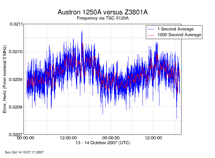
The Austron's frequency was monitored against an HP Z3801A GPS disciplined oscillator continuously for about 40 hours, starting about 18 hours before the first transmission run. A TSC-5120A test set, with a frequency counter resolution of 14 digits in 1 second, did the monitoring, with the output logged via computer.
Why didn't we use the Z3801A to directly drive the synthesizers? The problem is that the GPS part of a GPSDO only provides long term correction to the oscillator that it disciplines. For time spans less than a few thousand seconds, the system stability is primarily that of the free-running quartz oscillator, made perhaps a bit worse by any noise on the signal that provides frequency steering. So, there is no guarantee that over the period of the test, the GPSDO would be more stable than a good free-running oscillator like the Austron.
So, we used the Austron both for its short-term stability, and for the fact that it could be offset to avoid the trailing zeroes problem. Monitoring it against the Z3801A for a longer period (about 44 hours) let us determine its frequency offset without compromising the short term stability of the signal.
Here is a plot of the Austron versus Z3801A frequency, starting about 18 hours before the afternoon run, and ending about 14 hours after the evening run:
And here are close-ups of the period surrounding each test run:
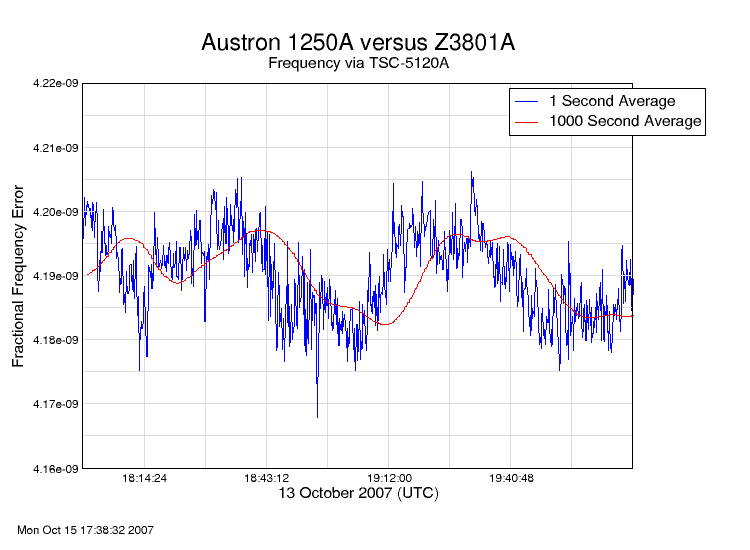
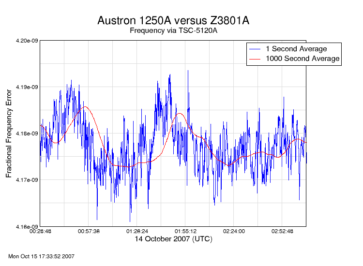
For the official results, we averaged the 1-second frequency readings during each test period to determine the offset during that run. As you can see, excluding one or two outliers the frequency was within 1.5x10⁻¹¹ during each test run. And, of course, we don't know how much of that was contributed by the Z3801A rather than the Austron.
B. Synthesizers
Three of the TADD-1 outputs drove the external reference inputs of a set of PTS 250-SX51 synthesizers. The PTS 250 normally has good, but not great, phase noise, and 1 Hertz frequency resolution. However, these three are a special version, the PTS 250/SX51 which has a unique mode: its normal 250 MHz output range can be divided by 10 to yield 0.1 Hertz resolution to a maximum 25 MHz output frequency, and this results in a very significant reduction in phase noise. Here's some information about the PTS synthesizers.
In the low-noise mode, the output is a square wave, and requires low pass filtering before it can be put on the air. As noted below, we used LPFs at two subsequent points to address this.
However, due to a communications error only the 30M synthesizer was used in low noise mode for the October 2007 test; the other two units ran in their normal mode with 1 Hertz resolution and normal phase noise.
C. Keying System
Here's Mike's description of the keying system:
"For the FMT we used PTS synthesizers to drive the three transmitters. The synthesizers did not have a way to key for CW so I needed a keying switch that would simultaneously key all three transmitters from a single source. For keying beacons I have used a 50-ohm RF switch from MiniCircuits (RSW-2-25P) so I used it in this application. The switch is a surface mount component that requires 5-volts.
"I followed up the switch with an MMIC (ERA-3SM) to give me a little more output. The ERA-3SM was probably not the best choice in this application as the output 1-DB compression point was lower than what we needed to drive the TS-520's. My original design allowed for keying the MMIC in addition to the switch. As it turned out keying the MMIC was not necessary as the RF switch had plenty of isolation. Also, the keying waveform was not as sharp if I left the MMIC powered. This reduced key clicks which was a concern. Three identical switches were on the circuit board. A common control line keyed the switches when grounded.
"I was originally going to use a PIC to key the keying matrix. I ran out of time to put the PIC hardware together. It was faster for me to write a VB.NET 2005 program to key the matrix from the serial port DTR line. This also gave me flexibility to change the program at the last minute if needed.
"The plan was to key CW to announce the test then have three ten minute key downs with CW ID between each. A final CW ID would follow at the end of the test. I figured the format of the CW would be debated up to the last minute so I needed to be able to change the text quickly. I also wanted a side tone from the PC as I figured I may not hear anything during transmit unless I had a receiver running.
"The main form for the program had text boxes for each CW text block. Each block had a default text string but that could be over written if needed. There was also an adjustable time for key downs incase we wanted something other than ten minutes. I actually set it to nine minutes to make sure we had an ID within a ten minute period. Each text box and key down could be individually selected with check boxes. To keep track of what was running each text box or key down changed color to green as it was in play. The CW speed was selectable with a default setting of 15 WPM. A single "START" button set the keying sequence in motion. At that point I could sit back and watch the show.
"The DTR keying and side tone code ran in separate threads. This improved the performance of the program. The system timer controlled the CW symbol timing and key down periods. The side tone used the Windows beep API to generate an 800 hz tone out of the PC speaker."
D. Transmitters and Antennas
The keying matrix outputs were amplified (using two buffer amps built by Bruce, ND8I, and one surplus Harris amplifier) to about +12dBm, which the transmitters require to generate full output power. A Mini-Circuits low pass filter was used after each buffer to knock any harmonics down to size.
Bruce modified two of the three Kenwood TS-520 transceivers that we used as amplifiers to get the signals up to the 100 watt level (Mike modified the third rig, based on Bruce's design). The idea was to use only the driver and final amplifier stages of the transmitter, bypassing the rest of the circuits (including all the oscillators). The mod is quite simple -- just lift one end of C21 (150pf) which couples into driver tube V1 (12BY7). Use RG-174 to connect from a new connector on the rear panel to the lifted end of C21. The shield goes to a ground pin that can be found near C21.
Bruce further modified one of rigs, which were made before hams got added frequency bands in the late 1970s, to operate on the 30M band.
The end result was that we could amplify the keyed synthesizer outputs to more than 100 watts on each of the three bands.
We were concerned that the long key-down period would cause heat problems, so Mike put additional fans on the transmitter stages.
We received the loan of an Ameritron AL-1200 amplifier, which we used on the 80M band for the first run; it caused some EMI problems, and we did not use it for the evening run.
The antennas were a wire vertical for 80M, with the feed point about 10 feet above ground and 8 radials; an inverted vee with the apex at 60 feet for 40M; and a sloper facing west, with the top at 50 feet, for 30M. An additional bandpass or low pass filter was in line before each of the antennas.