The MVUS FMT:
October 2007 Gallery
The W8KSE Station
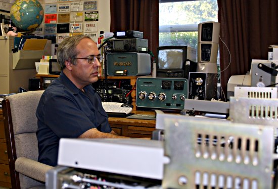
The FMT was hosted at Mike (W8RKO) Suhar's station; the W8KSE callsign belongs to the Midwest VHF/UHF Society. Here are some pictures of the setup.
(Here is a more detailed description of the station configuration.)
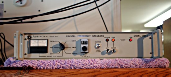
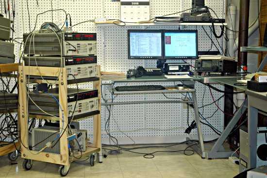
Starting at the beginning, here is the Austron 1250A frequency standard that provided the reference for all the transmitters.
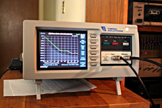
The standard's output fed a TSC-5120A test set which has a frequency counter providing 14 digits of resolution for a 1 second average. The 5120A's output was logged by a PC and processed to produce the frequency offset charts that were ultimately used to determine the exact transmission frequencies. The 5120A's reference input came from a Z3801A GPS disciplined oscillator. (The display here shows phase noise; it can do that while still providing frequency counter output via its ethernet port.)
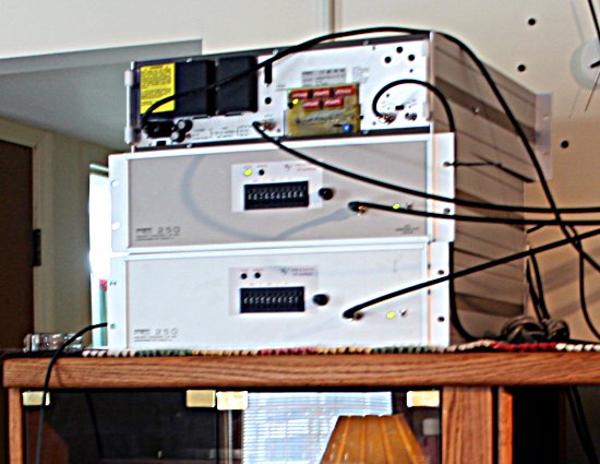
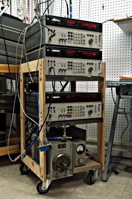
The Austron's main job was to feed three PTS-250 low noise synthesizers, one to drive each of the 80M, 40M, and 30M exciters. The bottom two have been modified with front-panel thumbwheel switches, but the top one lacked knobs and used a DIP-switch board for programming.
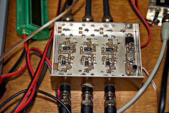
The synthesizer outputs were fed into a keying matrix designed and built by W8RKO which keyed all three lines simultaneously.
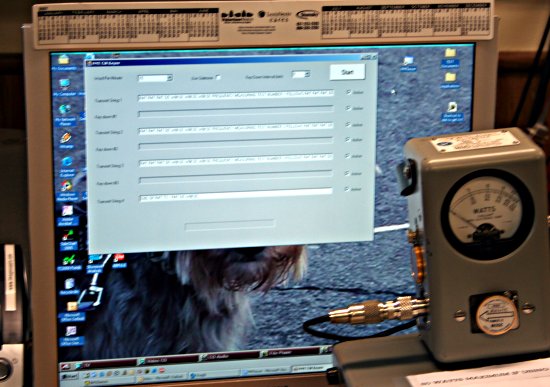
Here's the computer showing the software Mike wrote to send the CW messages and control the key-down periods.
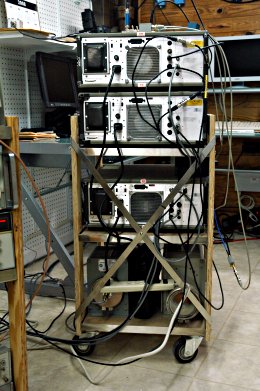
The matrix outputs fed buffer amplifiers which boosted the signal level so it could drive the RF stages.
Three Kenwood TS-520 transceivers, modified so that the buffered synthesizer inputs fed the driver and final stages directly, were used to get the signals up to 100 watts.
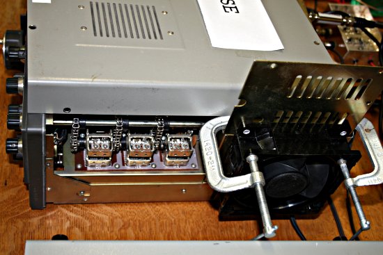
Mike did some extra engineering to help keep the rigs cool.
Lower than expected power output during the first run was tracked down to RF getting into the keying matrix. Adding some ferrites and bypass capacitors solved the problem.
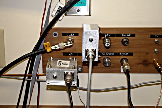
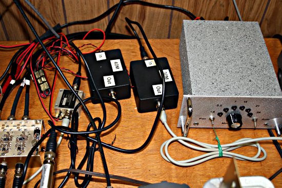
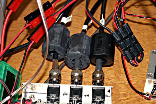
The transmitter outputs went into Mike's antenna patch panel, with some additional low pass filters to help keep things under control.
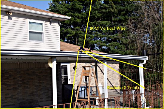
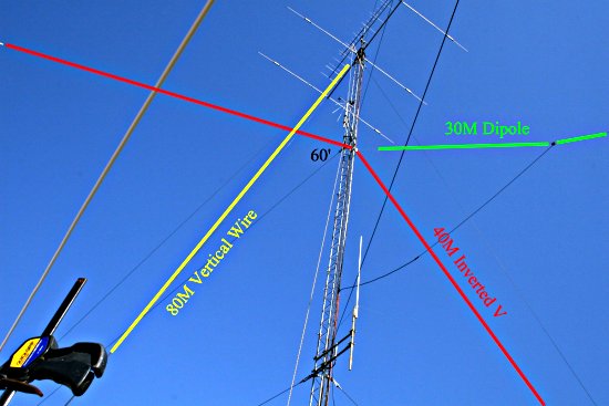
The 80M, 40M, and 30M antennas.
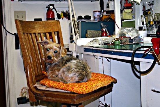
Jake kept the monsters away.
The N8UR Monitoring Station
John (N8UR) lives a couple of miles from W8RKO, and monitored the transmitted signals as a double-check on the system at Mike's. Out of 18 transmission segments, his off-the-air measurements differed from the calculated frequencies by a maximum of 0.376 milliHertz (and a minimum of 0.001 milliHertz). That's a worst case error of -6.1x10⁻¹¹.
John used three surplus HP 3586C selective voltmeters as receivers. They were all driven from an HP 5065A Rubidium frequency standard which is monitored continuously against GPS. The tracking generator output on the back of each receiver is looped, though an attenuator and 2-way splitter, into the antenna input to provide a marker signal. The audio output from each receiver is fed into one channel of a Delta-44 sound card. Doing this configuration for three receivers results in lots of jumper cables and paraphernalia!
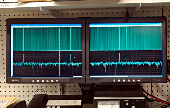
This shows the Baudline spectrum analyzer software displaying all three channels. The two peaks visible for each channel are the marker and the W8KSE signal. To get an idea of the frequency resolution this system allows, the two peaks are around 10 Hertz apart. The recorded audio was later analyzed with settings that put the two marker settings at the extreme left and right edges of the dual monitors; this allowed the difference between them to be measured with microHertz resolution.
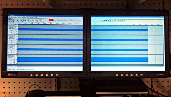
John used the Audacity audio editing tool to record the signals to .WAV files. The top three channels are the audio outputs of the three receivers; the bottom channel is the 1850 Hertz signal from an HP 3325B signal generator, locked to GPS, which was piped into the fourth channel of the sound card. This pilot tone allowed measurement and correction of the sound card's sample rate error.