Is This the World's Most Accurate
NTP Server Hardware?
Well, It's Right Up There, Anyway...
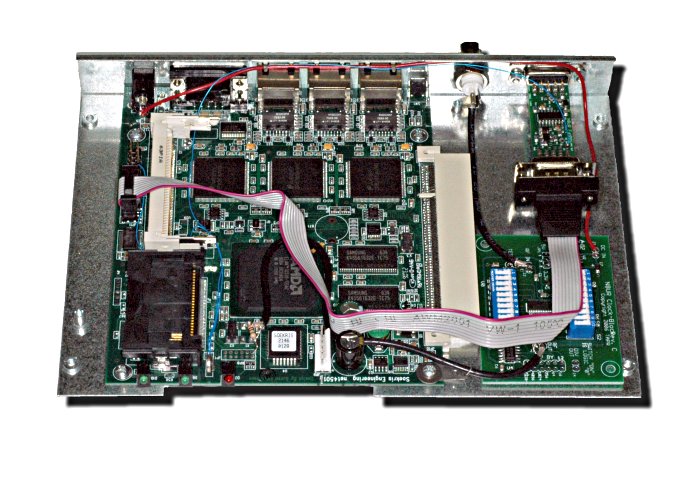
This is a Soekris net4501 computer modified to use a TAPR Clock-Block frequency synthesizer and a TAPR FatPPS signal conditioner.
When fed with a quality reference signal at 10MHz to drive the system clock, and a quality PPS signal to provide timetags, it can keep time to within a few hundred nanoseconds (here are plots of how my herd of Soekri are performing).
The secret to the net4501's timekeeping capability is its use of an AMD Elan SC520 CPU which has internal time registers with a resolution of about 100 nanoseconds. With a little hardware and software magic (figured out by Poul-Henning Kamp), this timer can be used to capture PPS timetags far more precisely, and with much less jitter, than the traditional method of using an RS-232 serial port control line as the input. The following two graphs show first, a comparison of the same PPS signal as captured by the net4501 serial port (blue trace) and as captured by the Elan timer (red trace), and then a close-up view of the Elan data. These plots cover about 10 hours of data.


Here are the outputs from ntpq -p and ntptime:
test1# ntpq -p
     remote           refid      st t when poll reach   delay   offset
jitter
==============================================================================
+GPS_HP(0)       .GPS.            0 l    1   16  377    0.000    5.768
1.712
oPPS(0)          .PPSZ.           0 l    2   16  377    0.000    0.000
0.015
+tick.febo.com   .PPSC.           1 u   53   64  377    0.990   -0.052
0.729
-tock.febo.com   .GPS.            1 u   61   64  377    1.012   -0.117
0.499
-toe.febo.com    .WWVB.           1 u   34   64  377    1.010   -1.593
0.447
-databox.febo.co 192.168.1.230    2 u   51   64  377    0.996    3.870
0.277
-timekeeper.febo 192.168.1.230    2 u    8   64  377    1.011    2.687
0.621
test1# ntptime
ntp_gettime() returns code 0 (OK)
  time c8e25a35.cd9a304c  Thu, Oct 19 2006 20:10:29.803, (.803134315),
  maximum error 2519 us, estimated error 15 us, TAI offset 0
ntp_adjtime() returns code 0 (OK)
  modes 0x0 (),
  offset 0.016 us, frequency -0.040 ppm, interval 1 s,
  maximum error 2519 us, estimated error 15 us,
  status 0x2001 (PLL,NANO),
  time constant 4, precision 0.001 us, tolerance 496 ppm,
This shows that the current offset between the system clock and the PPS stream is 0.16 microseconds, or 160 nanoseconds. The frequency error of -0.040 ppm is due to the fact that the synthesized clock frequency is offset 0.333... Hz from the integer value that the FreeBSD kernel uses in its calculations. The "jitter" and "estimated error" values are meaningless; they are the hard-coded minimums that NTP displays.
Note that my claim above is for the server hardware -- most of us use the reference NTP protocol implementation, ntpd, but Poul-Henning has written his own version, ntpns, which he convincingly claims offers much better performance when used with hardware like this. Unfortunately, at the moment ntpns doesn't support most of the reference clock hardware I'm using, so I'm not able to run it here.
How To Do It
WARNING: By installing these hardware mods, you will void the warranty on your Soekris computer at least four separate and distinct times. Proceed at your own risk!
Some preliminary notes:
- This assumes you're using
nanoBSD,
which is a stripped down version of FreeBSD.
- The PPS signal driving the Elan timer must be a positive pulse
(going from 0 volts to 5 volts at the on-time point) and must be at least
one timer tick long -- that means at least 1 millisecond (and
preferably 2 or 3 ms to allow room for error) if the "HZ" value in the kernel
is set to 1000 as recommended below. If your signal does not meet these
requirements, a TAPR
FatPPS
can condition the signal to these values. Mounting the FatPPS inside the
Soekris case makes for convenient access to the PPS signal, so you might
want to use it even if your PPS signal meets this requirement.
The Electrical Work
To implement high-performance timekeeping, you need to modify the net4501 board to accept an external clock signal, as well as use the high resolution timer. These steps require fairly good soldering skills as the surface mount components on the board are tiny; if you're unsure of yourself, find someone with SMT soldering experience to help you.
- Locate and remove the Soekris clock crystal (X1). A small heat gun is the
best way to do this, but with care a soldering iron and solder wick can be
used to lift the part. The only pin on X1 that we'll use is the one in
the upper left corner, so make sure you don't damage that solder pad.

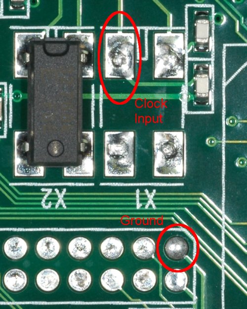
- A 100 ohm resistor provides a good load for the Clock-Block and also drops
its output signal enough to be compatible with the Soekris' 2.5
volt logic level. Wire up something like the piece of RG-174 cable and
resistor shown below. The cable should be long enough to reach the output
connector of the Clock-Block.

- Run a wire from the junction of R61/R62 (near the backup battery)
to one of the GPIO pins (I used PIO0, which is on JP3, pin 3).


- Run a second wire from the R61-R62 junction to the PPS source (e.g.,
the FatPPS output).
- Connect the RG-174 coax to the Clock-Block output.
- You can get power for the Clock-Block from the DC input jack:

- Configure the Clock-Block to generate 33.333333 MHz from your external
reference frequency; the
Clock-Block
Manual has programming information. Also, make sure the Clock-Block
is jumpered for 3.3 volt operation.
- If your reference clock provides a time code as well as a PPS signal, you can use a standard DB-9 ribbon cable to connect to J3; that's the input for the second serial port on the Soekris.
Modifying the Case
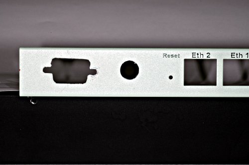
If you are using the standard Soekris case, you will need to drill a couple of holes in it. One is for the clock signal coming in to the Clock-Block board, and the second is for the PPS signal. The clock signal should probably use a BNC jack for easy connection, though any RF connector will work. A DB-9 connector (technically, a DE-9M) is best for the PPS signal, but cutting a hole for that shape requires either patience and skill with a drill and file, or a Greenlee chassis punch.
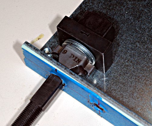
If you use a Greenlee punch to mount the FatPPS, you need to be careful to position the hole so that the punch parts will clear the various standoffs mounted inside the Soekris case. The best bet is to put the center of the pilot hole about 7/16 inch down from the top lip of the case, and about 1 1/32 inch in from the left edge. The BNC connector for the Clock-Block should be about 2 1/4 inches from the left edge.
The Greenlee punch is just a little too tall to fit under the top edge of the case. To get a clean punch, we added two 3/8 inch washers (7/8 inch outside diameter), with the center drilled out to 7/16 inch, to the punch assembly (see the photos to see how this is done). This allows the punch to drive all the way through the chassis without hitting the top lip.

Here's what the finished case looks like; it's really hard to keep the DB-9 punch aligned horizontally:
Software Configuration
-
Configure the kernel with:
Do not include:options CPU_ELAN # net4501 options CPU_ELAN_PPS # net4501 options CPU_SOEKRIS options GEOM_VOL options HZ=1000
because the kernel PPS sync is broken with the current FreeBSD 6.1 kernel and the Soekris hardware, and it doesn't do you any good in this configuration, anyway.options PPS_SYNC
- You need to set the GPIO pins using the sysctl command. A
"P" indicates an input on the specified pin. Using PIO0, the command
should be:
for the first (GPIO0) GPIO line.sysctl machdep.elan_gpio_config=-----P...--..--------..---------
- Create a symlink from /dev/elan-mmcr to /dev/pps0. (I added lines in /etc/rc.d/ntpd to issue the sysctl command and test for, and if necessary create, the symlink.)
-
Configure NTP to use the atom driver; you will need to tag another time
source with the "prefer" option to provide coarse timing. In the example
below, the coarse time and PPS both come from an HP Z3801A GPS disciplined
oscillator:
tos mindist 0.010

#Z3801A
server 127.127.26.0 ttl 1 prefer minpoll 4 maxpoll 4
fudge 127.127.26.0 time1 -0.960
fudge 127.127.26.0 refid GPS

# PPS -- since the HPGPS driver doesn't automagically enable it
server 127.127.22.0 minpoll 4 maxpoll 4
The tos mindist line is useful when the coarse time source has several milliseconds of jitter, which is the case with most ASCII timestamps. This parameter sets the maximum spread between prefer peer and the PPS source. Setting it to a higher value than the default of 1 millisecond helps reduce "clock-hopping" by allowing the prefer peer and the PPS source to have a wider offset -- serial port timestamps often have 5 ms or more of jitter. Setting it to 10 milliseconds, as shown in the example, should provide enough margin for most systems.
Burn the nanoBSD image to a CF card, insert it in the Soekris, and you should be ready to go.