The "White Box" 10GHz Local Oscillator
Introduction
A group of ham radio operators in the Midwest VHF/UHF Society are converting surplus microwave radios for use on the amateur 10GHz band. These radios are affectionately known as "White Boxes" (or is it "Whitebox"?) because they come in a heavy, weatherproof, industrial strength white enclosure. The pieces of the radio that we're actually using fill about 10 percent of that enclosure, and most of us have ripped those bits out and put them in a smaller box, but the name stuck.I have another page with more general info about the White Box modifications at https://febo.com/geekworks/whitebox.
I thought it would be interesting to characterize the performance of the crystal oscillator in the White Box. This isn't merely a theoretical exercise: the single sideband ("SSB") modulation we're using sounds garbled if the receiver and the transmitter aren't within 100 Hz or so of each other. At 10GHz, that's parts in 108, approaching frequency standard territory.
How the White Box Works
The White Box was designed as a data transceiver, but we're using only two of its components: the converter, which translates signals from the 10GHz range down to an intermediate frequency ("IF"), and the local oscillator ("LO") that drives the converter. The mixing process takes two signals and generates an output that includes both their sum and their difference (e.g., mixing a 10MHz and a 100MHz signal results in outputs at 90MHz and at 110MHz). A filter selects the desired output and attenuates the other.The converter works in both directions -- it accepts a signal at the IF frequency to create the transmitted signal at 10GHz, and it receives 10GHz signals and converts them down to the IF frequency. A 2 meter (144-148MHz) ham transceiver generates and receives the IF signals.
Our operating frequency is 10,368MHz. To convert this down to the 146MHz IF frequency, it must be mixed with either 10,222 or 10,514MHz. We're subtracting the operating frequency from the LO frequency (called "high side" injection), so the local oscillator needs to run at 10,514.00MHz.
Super-precise frequency accuracy isn't too critical in this application because the IF radio is tunable and can be adjusted to compensate for a reasonable amount of error (though if the frequency reading is more than a couple of kHz in error, searching for a weak signal becomes more difficult). However, the LO's frequency stability is important because the SSB mode requires the receiver and transmitter to stay in step with each other to 100Hz or better; otherwise, SSB signals become garbled. It's a real pain to constantly be tweaking the tuning to keep the signal sounding clear.
Test Methodology
To test the White Box LO, I used an HP 5340A microwave frequency counter. This is an ancient piece of test equipment that can be found on eBay for a reasonable cost. It's been around so long (at least since 1973) that the original version used Nixie tubes for the display, though mine is a fairly "new" 1981 version that uses a more modern-looking LED display. I'm using my GPS-steered oscillator as the frequency reference, so the frequency shown by the 5340A is, for all practical purposes, "right."While the 5340A is still a very useful instrument despite its age (mine is capable of measuring to 26GHz), it has one disadvantage for frequency stability measurement. Because of the way it converts microwave frequencies down to a range that normal frequency counter circuits can handle, it requires quite a long time to generate resolutions greater than 1kHz or so. The precise time depends on the input frequency, but at 10GHz a 1 hertz resolution (equivalent to 1x10¹⁰) reading requires about 65 seconds. Reducing the resolution by an order of magnitude also reduces the gate time by an order of magnitude, so for normal tuneup work this isn't a problem. But it does make it hard to track rapidly moving signals with high resolution, and it makes 1Hz resolution measurements a time consuming task.
To make matters a bit worse, the 100Hz resolution, which would allow more than one reading per second, isn't working in my unit. I'll fix that one of these days...
I've run two sets of measurements on the White Box LO. The first was right after the crystal was installed, and the second was after the unit had been running for about three weeks and had a chance to age a bit.
Initial Tests
Here's a plot of the LO output for the first 30 minutes after a cold start (the scale is 25kHz per vertical division):
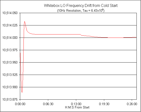
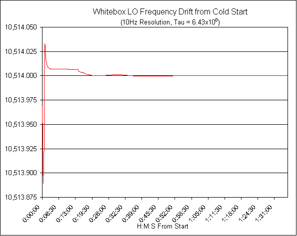
The wide swings at the beginning are probably due to the oscillator's phase lock loop trying to lock. The "tick" at about 13 minutes out is probably when the crystal heater reaches operating temperature. Here's a little bit longer view of the initial startup period, showing that the signal calms down pretty nicely after 20 minutes or so and stays put pretty well thereafter, at least at this scale:
The charts above show a relatively coarse frequency resolution; since a frequency shift of only tens of Hz is noticeable when listening to an SSB signal, I wanted to see what the drift looks like on a finer scale.
Below is a plot, with 1 Hertz resolution (and therefore about one sample per minute) covering 1 hour, after the oscillator had been running for a few hours. The frequency range is much narrower than in the earlier plots; each vertical division is only 50Hz.

With the exception of a couple of bumps, the short-term drift is about 50Hz in 15 minutes, which is thoroughly acceptable for almost any ham use.
However, I kept measuring the oscillator overnight, and the longer-term picture is quite different. Here is a chart showing not quite a full day of measurement, followed by a close-up of one interesting part of the plot (the scale for this and the following chart is 250Hz per vertical division):
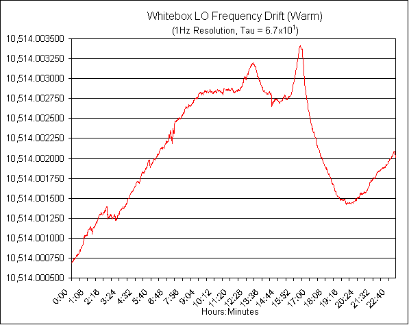
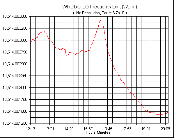
Everything looks fine until about 13 hours into the run, when the previously increasing frequency took a modest dip down, and then a very sharp upward turn a couple of hours later, followed by a very steep dip. The frequency went up about 600Hz in less than 40 minutes, and then took a nosedive of nearly 2kHz in about two hours before stablizing again. As far as I know, nothing in the test setup or the environment changed to result in this pronounced shift in the drift.
All crystal oscillators go through an "aging" process that results in a relatively linear frequency shift. This aging is most noticeable when the crystal is new; the amount reduces after the crystal has been running for weeks or months, and ultimately should be in the range of perhaps 10 to 100 Hz per day at this frequency. I think the behaviour we're seeing here is much more than just crystal aging.
The crystal in my oscillator is brand new, and in fact the whole unit was surplused by the manufacturer before ever being put into service. I suspect the sudden frequency shifts may be the result of something in the oscillator settling in after the unit was thoroughly heated up.
Results After Three Weeks' Burn-in
Here is a plot of 24 hours' data after the LO had been running continuously for about three weeks. You can see that it's stablized a lot, with the total frequency excursion being only about 200Hz over the 24 hours (the range is again 50Hz per vertical division).
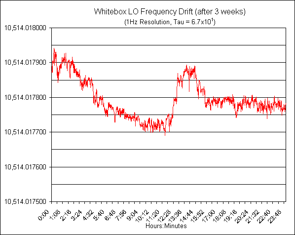
However, note that the frequency is now nearly 18kHz above the nominal 10514.00MHz. That indicates that there was a lot of drift during the two weeks the unit was left cooking between runs. It's probably a very good idea to let the LO and its crystal burn in for at least two or three weeks before final crystal "netting" to account for this initial aging.
Update: Since running the second tests, I've let the LO cook for another ten days or so, and have not seen further significant frequency shift. It looks like the initial two week burn-in was enough to take care of the lion's share of the aging.
Voltage Sensitivity
The White Box LO is quite sensitive to supply voltage. Here's a chart showing voltage versus frequency over the range 17 to 21 volts (the unmodified White Box uses 20 volts; most modifications have used 18 volts). The scale is 25kHz per vertical division.
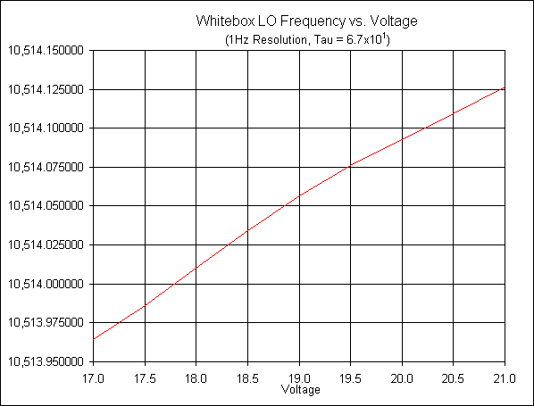
The frequency changes about 40kHz for every volt the supply changes. So, use a well-regulated power supply! It looks like the curve flattens out a bit above 19V, so running at higher than 18 volts may provide slightly better stability -- but it's not much of a difference.
By the way -- I also checked the LO power output against supply voltage. At 20 volts, the output of my unit (there's some variation) is 18dBm. At 18 volts, it's almost exactly 1dB down from that. Below about 17 volts, there's no output at all.
The Moral of the Story
The LO stabilizes fairly quickly from a cold start. After three or four minutes, it will be within a kHz or two, and after 15-20 minutes should be fully stable.
It's a good idea to let the LO "cook" for as long as possible -- ideally, several weeks -- to help it settle down and work any mechanical stresses out of its system.
Make sure you use a well regulated power supply, and ensure that there's no voltage shift between receive and transmit; otherwise you'll be operating in split frequency mode whether you want to or not! I think that a 20 volt supply is a better idea than running at 18 volts -- you'll pick up a dB of output.